
Planning Your Boiler Zoning System Install
A boiler zoning system install gives you independent temperature control in different areas of your building — so you’re not heating empty rooms or fighting over a single thermostat.
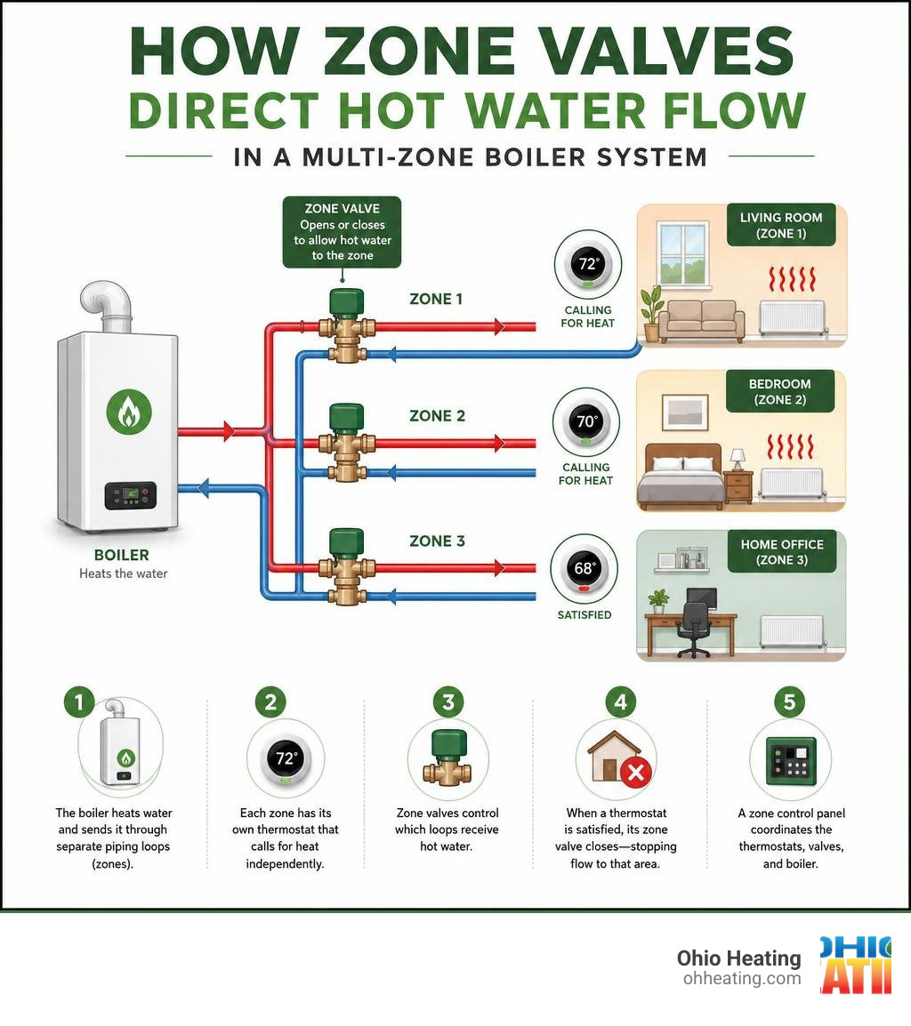
Here’s how a boiler zoning system install works, at a glance:
- The boiler heats water and sends it through separate piping loops (zones).
- Each zone has its own thermostat that calls for heat independently.
- Zone valves or dedicated circulator pumps control which loops receive hot water.
- When a thermostat is satisfied, its zone valve closes — stopping flow to that area.
- A zone control panel coordinates the thermostats, valves, and boiler.
This setup is more efficient than a single-zone system because you only heat the spaces that need it, when they need it. According to the U.S. Department of Energy, zoning can save up to 30% on typical heating bills.
The catch? A zoning system is only as good as its installation. Poor piping geometry, wrong valve placement, or an undersized circulator can turn a smart design into a noisy, inefficient headache — and some manufacturer schematics don’t even get it right out of the box.
I’m Jill Frattini, Service Coordinator at Ohio Heating in Columbus, OH, and I’ve spent years coordinating boiler service and installation projects — including complex boiler zoning system installs across Central Ohio properties. In this guide, I’ll walk you through exactly what it takes to get a zoned hydronic system done right.
Easy boiler zoning system install word list:
Before we pick up a pipe cutter or melt any solder, we have to map out the system. Designing a zoned hydronic system is all about understanding fluid dynamics and heat loads. We cannot simply split an old system into pieces without a clear strategy.
When planning your layout, the first rule of plumbing is that water always takes the path of least resistance. If you mix different pipe sizes — such as a 3/4-inch main line for your first floor and a 1/2-inch secondary line for a new bedroom addition — the hot water will naturally rush through the larger pipe. This leaves the smaller zone cold and starved of heat. Proper pipe sizing and balancing are absolute musts.
We also have to choose our zoning method. You can zone a boiler using either motorized zone valves or multiple circulator pumps. For a detailed breakdown of how to design these setups, you can consult the Zoning Design Guide. If you are starting from scratch or evaluating an upgrade for your Columbus home, our guide to Residential Boilers provides excellent context on modern hydronic equipment.
Here is a quick comparison table to help you decide which zoning method fits your home and budget:
| Feature | Zone Valves | Dedicated Circulator Pumps |
|---|---|---|
| Initial Cost | Lower (one pump, multiple inexpensive valves) | Higher (multiple pumps, larger manifold) |
| Electrical Load | Very low (uses 24VAC low-voltage power) | Higher (each pump draws 120V line voltage) |
| System Redundancy | Low (if the single main pump fails, the whole system goes down) | High (if one pump fails, other zones still heat) |
| Installation Space | Compact (fits easily in tight boiler closets) | Bulky (requires more wall space for pump manifolds) |
| Best Suited For | Small to mid-sized homes with standard heat loads | Large luxury homes, multi-family units, or high-head systems |
Key Components for a Boiler Zoning System Install
To execute a flawless installation, we need to understand the role of each component. Think of your zoned hydronic system as an orchestra, where every part must play in perfect harmony:
- The Boiler: The heart of the system that heats the water.
- Zone Valves: Motorized gates that open or close flow to specific piping loops based on thermostat demands.
- Circulator Pumps: The muscles that push hot water through the pipes.
- Thermostats: The brains that monitor room temperatures and signal when a zone needs heat.
- Zone Control Panel: The switchboard where all thermostat and valve wires terminate, coordinating calls for heat to ensure the boiler fires only when needed.
If you want to dive deeper into how these parts interact, check out our comprehensive guide, From Pumps to Valves: Everything You Need to Know About Boiler Parts.
Step-by-Step Guide to a Boiler Zoning System Install
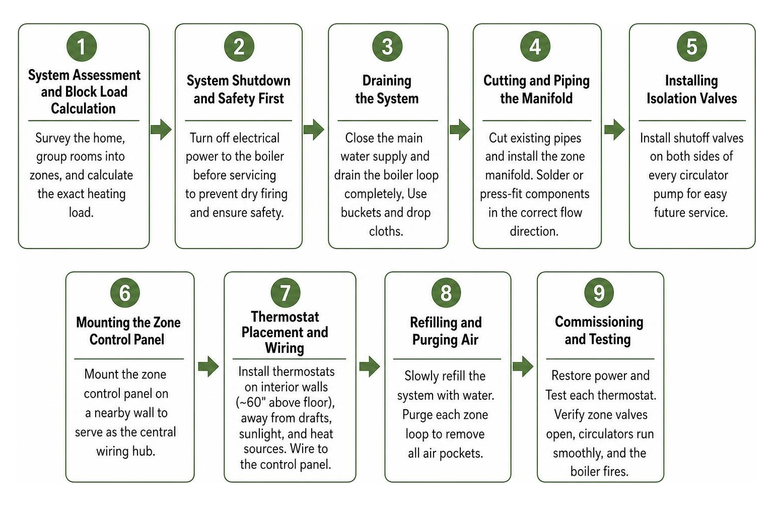
Ready to get your hands dirty? Here is the step-by-step process we follow at Ohio Heating to install a reliable zoning system:
- System Assessment and Block Load Calculation: We survey your home to group rooms with similar heating profiles (like keeping bedrooms on one zone and living spaces on another). We calculate the exact heating load to prevent oversizing.
- System Shutdown and Safety First: We turn off the electrical power switch to the boiler before touching the water supply. This is a critical safety step to prevent the burner from firing dry, which can crack a boiler block instantly.
- Draining the System: We close the main water supply and drain the boiler loop completely. We place buckets and drop cloths under the pipes to catch any residual, dirty water.
- Cutting and Piping the Manifold: We cut the existing copper pipes on the supply side of the system to install our new zone manifold. We solder or use press-fittings to install the new zone valves or circulators, making sure they are oriented in the correct direction of water flow.
- Installing Isolation Valves: We always install shutoff/isolation valves on both sides of every circulator pump. This best practice allows us to service or replace a pump in the future without needing to drain the entire system.
- Mounting the Zone Control Panel: We mount a centralized zone relay control panel on a nearby wall. This acts as the central hub for all low-voltage wiring.
- Thermostat Placement and Wiring: We install thermostats on interior walls, approximately 60 inches (5 feet) above the floor. We avoid placing them near drafty windows, direct sunlight, or heat sources like ovens. For detailed wiring layouts, you can refer to the Installation and Operating Instructions.
- Refilling and Purging Air: We slowly refill the system with water. Air is the natural enemy of hydronic systems, causing irritating banging noises and blocking heat transfer. We open the purging valves on each zone loop to push out every last pocket of air.
- Commissioning and Testing: We restore electrical power, turn on each thermostat one by one, and verify that the correct zone valve opens, the circulator runs smoothly, and the boiler fires up.
Piping Best Practices for Zoned Hydronic Systems
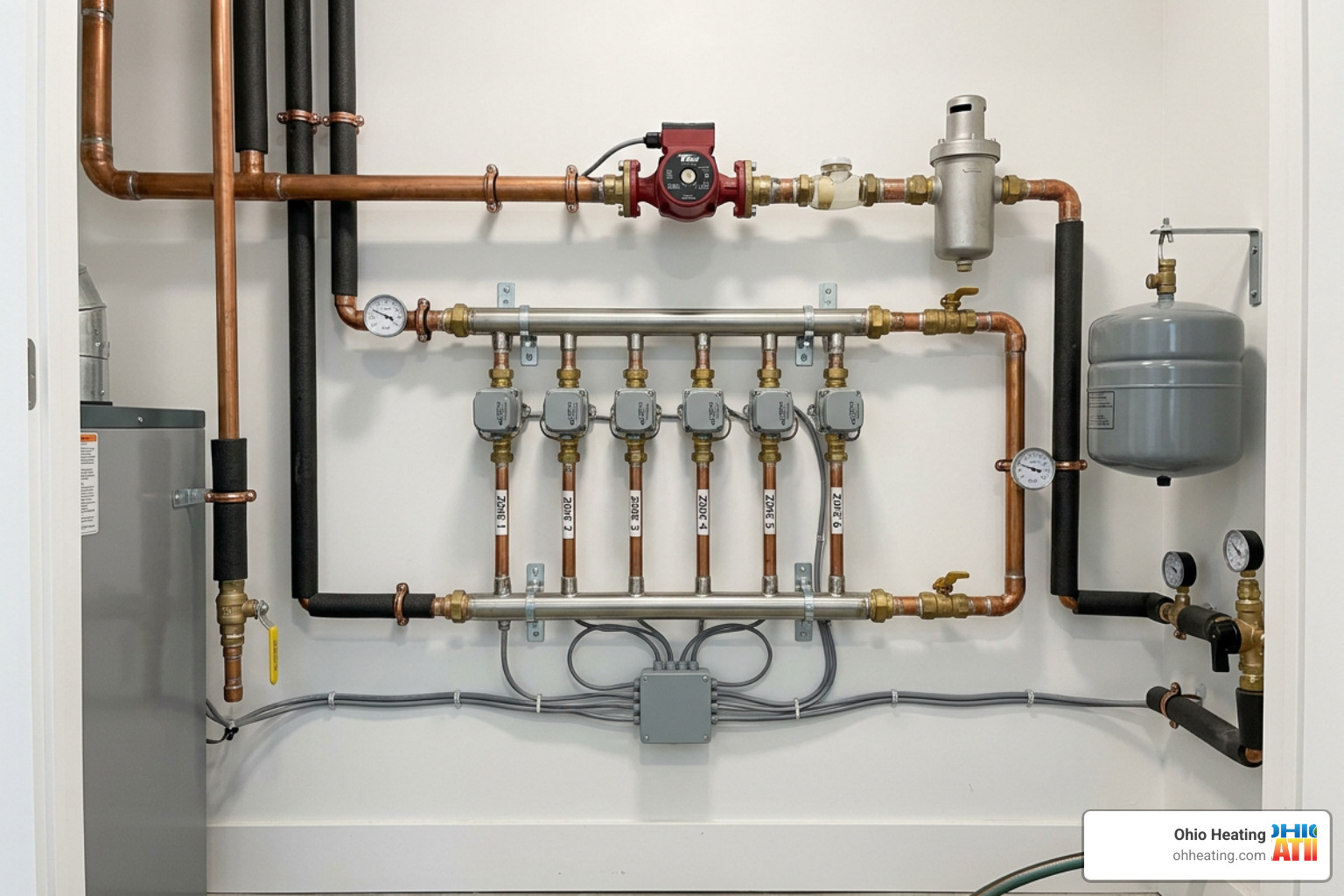
When it comes to piping a zoned system, many manufacturer manuals actually include flawed schematics. A common “glitch” in standard instructions is placing zone valves on the return side of the boiler or using poor piping geometry.
Let’s clear this up: zone valves should always be located on the supply side of the zone circuits.
If you place zone valves on the return side, you risk “heat migration.” This occurs when hot water naturally rises and seeps into inactive zones via the supply manifold, heating rooms that aren’t calling for heat. Placing the valves on the supply side blocks this unwanted gravity circulation.
Another critical error is using a bullhead tee to join return lines. A bullhead tee is a configuration where two return lines enter opposite sides of a tee fitting, slamming directly into each other before exiting through the branch. This creates immense turbulence, wastes circulator head pressure, and makes the system incredibly noisy. Always use a directional Y-fitting or space your tee connections along a common header to keep return flows smooth.
For properties with larger heating demands, you might even consider Implementing multiple boiler systems to maximize efficiency. To learn more about local installation standards, read our Boiler Installation Insights for Columbus Homeowners.
Circulator Placement and Straight Pipe Requirements
To prevent turbulent flow and premature pump failure, we must follow strict physical piping guidelines:
- The 12-Diameter Rule: You must provide at least 12 diameters of straight pipe leading directly into the inlet of any circulator pump. For a standard 3/4-inch copper pipe, this means about 9 inches of straight, unobstructed pipe before the pump. This allows the water to transition from a turbulent state into a smooth, laminar flow, maximizing pump performance and eliminating velocity noise.
- Pumping Away from the Expansion Tank: Always position your circulator pump so that it is “pumping away” from the connection point of the system’s expansion tank. The expansion tank is the point of no pressure change in a hydronic loop. Pumping away from this point forces the pump to increase system pressure when it runs, which helps push air out of the lines. If you pump toward the expansion tank, the pump will drop the system pressure, which can cause air bubbles to form and create cavitation in your pipes.
Managing Pressure and Flow in Zoned Boilers
When you have multiple zones, the flow dynamics of your system change constantly. If you have a three-zone system and only one zone is open, a standard single-speed circulator pump will try to push 100% of its water volume through that single, narrow loop. This causes high water velocity, whistling pipes, and puts excessive stress on your zone valves.
To manage this differential pressure, we have two primary solutions:
- Pressure-Regulated, Variable-Speed Circulators (ECM Pumps): These modern smart pumps automatically sense the resistance in your lines. If only one zone opens, the pump slows down to match the exact flow requirement of that single loop, saving electricity and eliminating noise.
- Differential Pressure Bypass Valves: If you are using a traditional single-speed pump, we install a bypass valve between the supply and return manifolds. When pressure builds up because multiple zone valves close, this spring-loaded valve opens, safely redirecting excess hot water back to the boiler’s return side.
For more information on managing these forces, check out our guide on Pressure and Temperature Control Valves.
Conventional Controls and Wiring
Once the physical piping is complete, we have to wire the system. We use a low-voltage zone relay control panel to act as the brain. This panel isolates the high-voltage (120VAC) power needed to run the boiler and pumps from the safe, low-voltage (24VAC) lines running to your thermostats.
We use high-quality, 22-gauge or larger thermostat wire for standard runs, upgrading to 20-gauge or larger for runs exceeding 100 feet. We also calculate the total power load (VA) of our motorized zone valves. If the power draw of your valves exceeds the capacity of the boiler’s internal transformer, we install an auxiliary 24VAC transformer to prevent system overloads. To explore these electrical setups further, read about our Conventional Controls options.
Frequently Asked Questions about Boiler Zoning
Where should zone valves be located in a multi-zone system?
Zone valves should always be installed on the supply side of your zone circuits. Placing them here blocks hot water from naturally migrating into inactive piping loops when other zones are running. This ensures that only the rooms calling for heat actually get warm, saving energy and preventing uneven temperatures.
Why must a bullhead tee be avoided in hydronic piping?
A bullhead tee occurs when two opposing return lines run directly into each other at a tee fitting. This causes the water flows to collide, creating heavy turbulence, air pockets, and loud banging or whistling noises. It also wastes the circulator pump’s energy. Instead, return lines should enter a common manifold header spaced apart, allowing the water to flow smoothly in the same direction.
How much straight pipe is required before a circulator pump?
You should always have at least 12 pipe diameters of straight, unobstructed pipe directly before the inlet of a circulator pump. This allows turbulent water coming around elbows or valves to settle into a smooth, laminar flow pattern before entering the pump impeller, which reduces wear and tear and keeps your system whisper-quiet.
Conclusion
A boiler zoning system install is one of the best investments you can make for your home’s comfort and your energy bills. However, hydronic heating is a science. Getting the piping geometry right, preventing heat migration, and ensuring proper electrical controls require specialized training and real-world experience.
At Ohio Heating, we have been serving Columbus, Central Ohio, and the surrounding areas since 1999. Our team of certified technicians is dedicated to ensuring your heating system is installed to the highest standards of safety and operational reliability.
Don’t leave your winter comfort to guesswork. Schedule expert boiler sales and service with Ohio Heating today, and let us help you design the perfect zoning system for your home!