
The Silent Brain Behind Your Building’s Cooling System
An air handling unit controller is the digital brain that tells your commercial air conditioning system exactly when to cool, how much air to move, and how to keep indoor conditions comfortable — automatically, around the clock.
If you manage a commercial building and want a quick answer:
| Question | Quick Answer |
|---|---|
| What does it do? | Controls fans, cooling stages, dampers, and sensors in an air handling unit |
| Who needs one? | Any commercial or institutional building with a central air conditioning system |
| How does it communicate? | Via BACnet MS/TP, BACnet IP, Modbus, or legacy protocols like N2 Bus |
| Can it connect to a BMS? | Yes — it integrates directly with building management systems |
| Why does it matter? | It protects occupant comfort, improves energy efficiency, and prevents costly equipment failures |
Most building owners never think about their AHU controller — until something goes wrong. When cooling fails in a commercial space, the consequences are immediate: uncomfortable tenants, disrupted operations, and expensive emergency repairs. The controller is the component that prevents all of that.
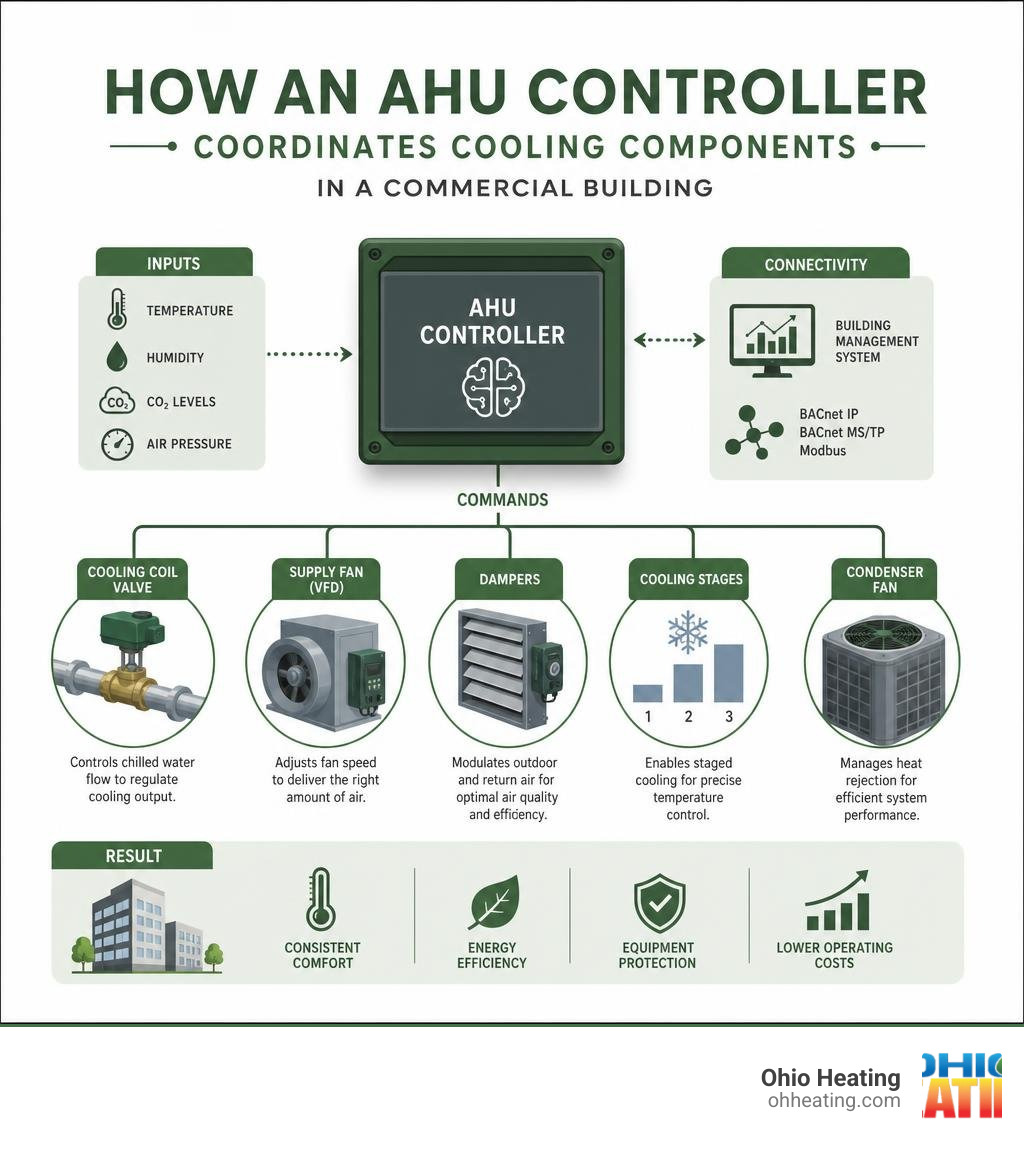
Modern AHU controllers — like the US5182 or the Johnson Controls AHU103 — manage dozens of inputs and outputs simultaneously. They read temperature, humidity, CO2, and pressure sensors. They command dampers, valves, and variable-frequency drives. And they do it all while staying in sync with the rest of your building’s systems.
This guide breaks down exactly how these controllers work, what to look for in the hardware, and how to install, wire, and troubleshoot them correctly.
I’m Jill Frattini, Service Coordinator at Ohio Heating in Columbus, OH, where I work closely with our commercial AC teams on projects involving building automation and air handling unit controller upgrades across Central Ohio. With years of hands-on coordination experience in the air conditioning industry, I’ve seen how the right controller — properly installed and configured — can be the difference between a building that runs smoothly and one that doesn’t.
Key air handling unit controller vocabulary:
What is an Air Handling Unit Controller and How Does It Manage Cooling?
An air handling unit controller is a specialized Direct Digital Control (DDC) microprocessor designed to automate the cooling, ventilation, and air circulation processes within an air handling unit (AHU). Unlike simple residential thermostats that merely turn a cooling system on or off, an AHU controller manages a complex, multi-variable cooling environment. It continuously monitors physical conditions inside and outside the building, processing these inputs in real-time to adjust air conditioning components with high precision.
At its core, the controller regulates the entire cooling cycle. It determines how much warm indoor air is exhausted, how much fresh outdoor air is introduced, and how much refrigerant or chilled water is utilized to lower the air temperature before it is distributed. By coordinating these variables, the controller maintains consistent indoor temperatures, manages humidity levels, and ensures proper air circulation. For a deeper understanding of the physical components managed by these systems, check out The Ultimate Guide to Air Handler Control Units and Boards.
Core Cooling Functions of an Air Handling Unit Controller
To keep a commercial facility cool and comfortable, the controller manages several primary mechanical functions:
- Cooling Stage Sequencing: The controller manages multiple cooling stages to match the building’s thermal load. For systems utilizing Direct Expansion (DX) cooling, it can sequence up to six compressor stages to prevent short-cycling and reduce energy spikes. In chilled water systems, it modulates a 0-10 VDC or 4-20 mA control valve to regulate the flow of chilled water through the cooling coil.
- Fan Speed and Volume Control: By interfacing with Variable Frequency Drives (VFDs) or electronically commutated motors (ECMs), the controller adjusts fan speeds based on static pressure or cooling demand. This ensures the correct volume of conditioned air is delivered to the space without wasting fan power.
- Damper Modulation: The controller continuously adjusts outdoor air, return air, and exhaust air dampers. This maintains ventilation requirements while optimizing the mixing of air streams for efficient cooling.
For those interested in the deep engineering details of these operational sequences, the Air Handling Unit (AHU) Controller Technical Bulletin provides comprehensive documentation on standard factory programs.
Configurable Cooling Applications
Advanced controllers are highly versatile and can be configured to execute specialized cooling and ventilation strategies:
- Economizer Control: This strategy uses cool outdoor air for “free cooling” when environmental conditions permit. The controller compares outdoor air temperature (or total enthalpy) to return air conditions. If the outdoor air is cool and dry enough, the mechanical cooling stages are disabled, and the outdoor air dampers open fully to cool the building.
- Demand-Controlled Ventilation (DCV): By monitoring indoor carbon dioxide (CO2) levels, the controller adjusts the minimum outdoor air damper position. When occupancy is low and CO2 levels are well within safe limits, the controller reduces the intake of hot outdoor air, significantly lowering the mechanical cooling load.
- VFD Modulation and Static Pressure Matching: The controller modulates the supply fan speed to maintain a constant duct static pressure setpoint. As variable air volume (VAV) boxes throughout the building close their dampers, the static pressure in the main duct rises. The controller detects this change and slows down the fan, reducing energy consumption.
Implementing these advanced sequences is one of the most effective ways to lower utility bills. To see how these strategies fit into a broader facility management plan, read about Commercial AC Control Systems Don’t Let Your Building Have a Meltdown.
Hardware Specifications and Sensor Integration for AC Systems
A professional air handling unit controller must possess robust physical hardware and precise processing capabilities to survive the harsh electrical and physical environments of mechanical rooms. Modern programmable platforms, such as the Universal programmable controller – Alsmart® | Danfoss, feature modular hardware architectures that scale from simple single-fan ventilation units to massive, multi-stage custom air handlers.
These controllers must operate reliably in ambient temperatures ranging from 0 to 50°C (32 to 122°F) and non-condensing relative humidity levels between 10% and 90%. They typically require a supply voltage of 24 VAC (nominal 20-30 VAC) at 50 or 60 Hz, consuming up to 16 VA of power (excluding external valve and relay loads). To protect sensitive digital electronics, high-quality controllers utilize split-board designs where the processing board plugs into a separate, pre-wired base terminal board.
Input and Output Configurations for Cooling Components
The capability of an AHU controller is largely defined by its physical input and output (I/O) point capacity. For example, a robust commercial controller like the US5182 features 6 RTD inputs, 6 digital inputs, 8 analog inputs, 8 digital outputs, and 6 analog outputs.
To ensure precise control over cooling valves and VFDs, the controller’s analog inputs feature a high 15-bit resolution and a fast 1.5-second sample time. This allows the controller to detect minute temperature fluctuations as small as ±0.4°F with silicon sensors, adjusting cooling outputs before occupants notice a change.
| Input/Output Type | Standard Signal / Electrical Specs | Common Cooling System Application |
|---|---|---|
| Analog Input (AI) | 0-10 VDC, 4-20 mA, or Platinum/Nickel RTD | Temperature sensors, humidity transmitters, static pressure transducers |
| Binary Input (BI) | Dry contact, current switch | Fan status, filter pressure switches, manual override switches |
| Analog Output (AO) | 0-10 VDC or 0-20 mA | Modulating chilled water valves, VFD speed commands, damper actuators |
| Binary Output (BO) | 24 VAC Triac or Dry Contact Relay | Compressor contactors, condenser fan starters, alarm indicators |
Essential AC Sensors and Their Strategic Locations
To optimize cooling performance, an air handling unit controller relies on a network of strategically placed sensors throughout the air stream:
- Discharge Air Temperature Sensor: Located in the supply duct downstream of the cooling coil and supply fan. This sensor provides the primary feedback loop for modulating the cooling valves or staging compressors to maintain the supply air setpoint (typically 55°F).
- Return Air Temperature and Humidity Sensors: Placed in the return air duct before the mixing box. These sensors represent the average comfort conditions of the occupied space and are used to calculate total enthalpy for economizer control.
- Mixed Air Sensor: Positioned downstream of the mixing box but upstream of the cooling coil. This sensor measures the temperature of the combined outdoor and return air streams, allowing the controller to verify proper damper mixing.
- Outdoor Air Temperature and Humidity Sensors: Mounted on the exterior of the building, protected by a sun shield to prevent solar radiation from skewing the readings. These are critical for determining economizer eligibility.
- Duct Static Pressure Transducer: Installed approximately two-thirds of the way down the main supply duct. It measures the physical air pressure in the duct, allowing the controller to modulate the supply fan VFD.
- Differential Pressure Switch (Filter Status): Measures the pressure drop across the air filters. When dust builds up and restricts airflow, the pressure drop increases, tripping the switch and sending a “dirty filter” alarm to the controller.
Installation, Wiring, and Noise Mitigation for Reliable AC Control
Installing an air handling unit controller requires strict adherence to physical and electrical standards. Incorrect mounting or sloppy wiring can introduce electrical noise, leading to erratic sensor readings, dropped network communications, or premature hardware failure. To understand how professional installation fits into overall system design, see Mastering the Art of AC Control Systems.
Mounting and Power Wiring Best Practices
The controller enclosure must be mounted securely to a solid, non-vibrating vertical wall or inside a dedicated mechanical control panel. Avoid mounting the enclosure directly to the vibrating sheet metal of the air handler casing.
When wiring the 24 VAC power supply, always use a dedicated, isolated transformer. We highly recommend utilizing split-bobbin transformers, which provide inherent transient immunity by physically separating the primary (120 VAC) and secondary (24 VAC) coils on side-by-side bobbins.
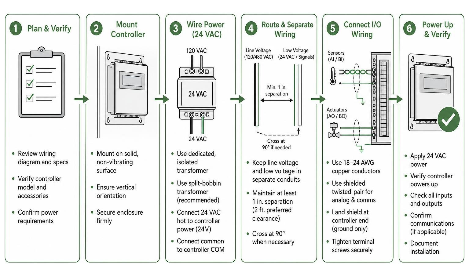
Always separate line-voltage wiring (such as 120/480 VAC motor power) from low-voltage control wiring (24 VAC and sensor signals) by a minimum of one inch. Run them in separate conduits. Additionally, keep low-voltage signal wiring at least one foot (two feet is preferred) away from high-voltage power lines to prevent electromagnetic coupling.
Wiring Sensors and Actuators to the Air Handling Unit Controller
When connecting sensors and actuators to the controller’s terminal board, use only high-quality copper conductors of 18 to 24 AWG. For analog inputs and communication lines, shielded twisted-pair cabling is mandatory to prevent electrical noise from corrupting the signals.
- Shield Grounding: Connect the cable shield to a verified earth ground at the controller end only. Leave the shield floating (unconnected and insulated) at the sensor or actuator end. Grounding both ends of a shield creates a ground loop, which can introduce severe electrical interference.
- Inductive Load Suppression: Devices with inductive coils, such as large motor starters or solenoid valves, release high-voltage spikes when they are switched off. To prevent these transients from disrupting the controller, install transient suppression devices (such as Metal Oxide Varistors [MOVs] or RC snubbers) directly across the coil terminals of the inductive load, rather than at the controller.
- Isolated Commons: Ensure that all analog and binary commons on the controller terminal board remain completely isolated from earth ground and the 24 VAC power supply neutral.
For more detailed technical guidelines on field wiring and controller terminations, explore The Ultimate Guide to AC Control Systems.
Networking and BMS Integration via BACnet and Legacy Protocols
In modern commercial facilities, an air handling unit controller rarely operates in isolation. It is typically networked with other field controllers and integrated into a centralized Building Management System (BMS). This connectivity allows facility managers to monitor cooling performance, adjust setpoints remotely, and receive real-time alarms from a single workstation. To learn more about how networked controls drive commercial efficiency, read about Commercial AC Services Building and Energy Management.
Integrating with Building Management Systems (BMS)
Modern controllers support standard, open communication protocols to ensure seamless integration with third-party BMS platforms:
- BACnet MS/TP: A master-slave/token-passing protocol operating over a physical RS-485 serial network. It is the industry standard for field-level device communication.
- BACnet IP: Communicates over standard Ethernet networks, providing high-speed data transmission and direct web-browser access to the controller.
- Modbus RTU / TCP: Widely used for integrating specialized equipment like VFDs, electrical meters, and smart sensors directly into the AHU controller.
- Legacy Protocols (N2 Bus): Many older facilities still utilize legacy field buses like the Johnson Controls N2 Bus. Advanced upgrade controllers (like the US5182) feature dual-protocol chips, allowing them to communicate on legacy N2 networks today while remaining fully compatible with future BACnet upgrades.
Daisy-Chaining and Addressing Multiple Controllers
When networking multiple controllers via an RS-485 network (such as BACnet MS/TP or N2 Bus), the devices must be wired in a continuous “daisy-chain” configuration.

- No T-Taps or Y-Connections: Wiring must run directly from the controller terminal block to the next controller. Branching, star, or “T” connections cause signal reflections that corrupt network communications.
- End-of-Line (EOL) Termination: The physical ends of the communication bus must be terminated. This is accomplished by setting a physical EOL switch or jumper on the very first and very last controller in the daisy chain. EOL terminators match the characteristic impedance of the cable, preventing signal reflections.
- Hardware Addressing: Every controller on the network segment must have a unique hardware address. On legacy or standard MS/TP controllers, this is set using physical DIP switches on the circuit board before powering up the system.
- Segment Limits: A standard N2 Bus segment can support up to 50 devices with a maximum wire run of 1,524 meters (5,000 feet) without repeaters. With two repeaters, the network can be extended up to 4,572 meters (15,000 feet).
Commissioning, Diagnostics, and Troubleshooting AC Controllers
Once installation and wiring are complete, the air handling unit controller must be systematically commissioned to verify that all cooling sequences operate exactly as designed. This process ensures that dampers stroke fully, cooling valves modulate smoothly, and safety limits trip reliably. Proper commissioning is also a prerequisite for accurate system balancing; you can read more about this in our guide to AC Air Balancing.
Configuration and Commissioning Software
Legacy and some modern proprietary controllers are configured using dedicated software tools, such as Johnson Controls’ HVAC PRO for Windows. Instead of requiring complex line-by-line coding, these tools use a structured question-and-answer wizard. The technician answers questions regarding the physical configuration of the AHU (e.g., “Is there a modulating cooling valve?”, “How many stages of DX cooling are present?”), and the software automatically selects and compiles proven control logic from an extensive library.
Once the configuration file is generated, it is downloaded to the controller’s non-volatile EEPROM memory. Because the program is saved in EEPROM, the controller retains its entire configuration and operational parameters indefinitely during power outages, eliminating the need to reload software when power is restored.
Troubleshooting Ground Loops and Communication Errors
When a controller fails to communicate or displays erratic behavior, technicians use systematic diagnostic steps to isolate the issue:
- Diagnosing Ground Loops: If sensor readings drift or jump erratically, use a digital multimeter to measure the AC voltage between the controller’s sensor common terminal and a verified physical earth ground. Any reading above 0.5 VAC indicates a ground loop. To resolve this, locate the sensor or actuator that has its shield grounded at both ends, or find where a low-voltage common wire has accidentally come into contact with the metal AHU casing.
- Resolving Communication Drops: If a controller drops off the BACnet or N2 network, check the physical line voltage at the end-of-line controllers. Verify that the EOL switches are enabled only on the physical ends of the daisy chain. Use an oscilloscope or network diagnostic tool to check for RS-485 bias voltage; a healthy idle network should show a stable DC differential voltage between the positive (+) and negative (-) data lines.
- Power-Up Self-Test Failures: When first powered on, the controller executes an internal self-test of its processor, RAM, and EEPROM. If the status LED flashes a self-test error code, disconnect all field terminal blocks to rule out external short circuits. If the error persists with all field wiring removed, the internal processor has failed, and the electronics board must be replaced.
Frequently Asked Questions About AHU Controllers
How does an AHU controller optimize AC energy efficiency?
An air handling unit controller maximizes cooling efficiency through several automated strategies. First, it utilizes economizer cooling, opening outdoor air dampers to cool the building with natural outdoor air whenever the temperature and humidity are favorable, keeping the energy-intensive compressors off.
Second, it uses VFD fan control to continuously adjust the supply fan speed to match the actual static pressure requirements of the building, saving significant fan motor energy.
Finally, through Demand-Controlled Ventilation, it monitors CO2 levels to limit the intake of hot, humid outdoor air during periods of low occupancy, directly reducing the load on the air conditioning system.
What is the difference between an AHU controller and a standard thermostat?
While a standard thermostat simply monitors space temperature and turns a single cooling system on or off, an air handling unit controller is a highly sophisticated, multi-point Direct Digital Control (DDC) system.
It manages dozens of inputs and outputs simultaneously, executing complex proportional-integral-derivative (PID) control loops to modulate chilled water valves, sequence multiple cooling stages, adjust variable-speed fans, and control mixed-air dampers. Additionally, AHU controllers are fully programmable, feature built-in diagnostic safety sequences, and integrate directly into centralized building management networks.
How do you prevent electrical noise from disrupting the controller?
To protect an AHU controller from electrical interference, always install low-voltage control and communication wiring in separate conduits from high-voltage power lines, maintaining a physical separation of at least one foot. Use shielded twisted-pair cabling for all sensor and network lines, grounding the shield at the controller end only.
Additionally, use an isolated, split-bobbin transformer to power the controller, and install transient suppressors (like MOVs) directly across the coils of any nearby inductive loads, such as motor starters or contactors.
Conclusion
An air handling unit controller is the single most critical component for ensuring reliable, energy-efficient cooling in commercial buildings. When properly installed, wired, and networked, these digital brains maintain perfect indoor comfort, protect expensive cooling equipment, and drastically lower monthly utility bills. However, because these systems interface with complex building automation networks, their installation and programming require specialized commercial expertise.
At Ohio Heating, we have been providing expert commercial AC installation, repair, and preventative maintenance across Columbus and Central Ohio since 1999. Our dedicated team specializes in building automation, control retrofits, and system integration, ensuring your facility remains reliable and comfortable even during the hottest summer days.
If you are ready to upgrade your building’s cooling controls or need expert assistance troubleshooting an existing system, contact us today to discuss our tailored solutions for Ohio Control Solutions Conventional Controls.